
Table of contents
LED Dimmer
Smart LED Dimmer project to control up to 5 5V / 3V led strips and lights.
Introduction
I really like illuminated book nooks, LEGO led kits and other small led string lights. However, they are mainly battery powered, using 2 or 3 AA or AAA batteries and have a manual switch to turn them on and off. If you have multiple of them it either takes time to switch them on and off everyday or you just don’t do it anymore after a certain time.
Since I have a smart home (or at least smart lighting), I wanted to smartify this. Because they are low current, I wanted to have a single connected device to control multiple lights. Having a device for each small light felt like a waste of bandwidth, materials and money. Unfortunately I was not able to find one with multiple outputs, offered 5V output and per channel dimming.
Custom Dimmer
So the goal is simple. Make a device that can control up to 5 different LED strips to replace battery packs and offer an additional dimming option.
Since we are building a device that will need to output a max of 5V with not a lot of current draw, we can make it USB powered so simplify things. On top of this, to simplify adoption I want multiple options for control :
- Buttons on device
- Web page on local Wifi
- Zigbee
- Matter-Over-Wifi
- Matter-Over-Thread
This way, the state of your smart home doesn’t matter (pun intended), even if it is your only device you can use it fully.
Hardware
PCB
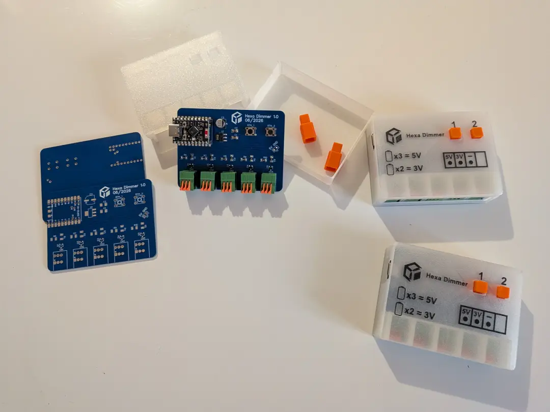
I wanted to make multiple units of the final products, and to make something clean, I decided to make a custom PCB.
I used EasyEDA to design the PCB instead of KiCad even if I have experience with both simply because it makes ordering to JLCPCB easier.
I am not using components smaller than 1206 to keep it hand-solderable and besides, there is no need to make it tinier there is a lot of space available.
I added an additional header pin to put a separate USB-C port so that plugin unplugin doesn’t wear it out. In the end i did not put it in the design because it was making the 3D design harder and I figured it wasn’t essential since I could just use the one on the dev-board.
Speaking of the dev-board, the module is an ESP32-C6 Mini, with a wifi, zigbee and thread radio, ideal for those IoT projects. Having a dedicated dev-board for the chip makes it easier to swap it out to test a different firmware or if the board fries.
There is a 3.3V regulator (to avoid stressing the one on the deb-board with too much current draw), and each transistors pulls down and is controlled by a pin of the ESP chip.
The connectors used ar toolless, you just have to push the orange clip to insert or remove a cable. I wanted this kind of connector to make it easier to install or change you configuration but I am a little bit disappointed in their holding strength; I think screw terminal would have been a better choice in the end. Anyway their footprint are compatible so no PCB redesign is needed.
The connectors have 3 ports each : 5V, 3V3 and common GND. So you plug the negative wire in the GND port and plug the positive wire in either the 5V or 3V3 port depending on your light.
Caution
3 batteries in series make 4.5V and 2 make 3V. This device supplies 5V and 3.3V so it is a little bit higher. Depending on the quality of the led circuit, this can make the leds draw more current and shorten their lifespan. If you have any doubt, you can add a current limiting resistor.
Finally, I added 2 buttons to have local control :
- The first one cycles through brightnesses :
OFF-25%-50%-100% - The second one cycles through the outputs:
Channel_1-Channel_2-Channel_3-Channel_4-Channel_5
Enclosure
For the enclosure I wanted to make something clean and since I took the time to make the PCB look nice, I use transparent PLA to show off a little bit of the electronics. I used orange PLA for the buttons and the design snaps when closed without any tools. To open the case you just have to gently press on the sides to remove the top part.
Using transparent PLA also allowed a cool trick : I wanted to use black PLA to add text and symbols so that you do not need a manual to use it. I wanted to use the multicolor printing capabilities of my 3D printer to make it smooth in 1 piece but having this fine text printed with a 0.2mm nozzle made it really hard to stick on the build plate.
So instead of printing the black text directly on the PEI plate, I first printed 1 layer of the transparent PLA cover and embedded the black PLA inside, witch help it a lot to stick and to have a clean result.
Software
On the software side, as stated before, I wanted to make 4 different versions.
- Web page on local Wifi
- Zigbee
- Matter-Over-Wifi
- Matter-Over-Thread
Web page on local Wifi
For this one, it was the simplest, I knew that using ESPHome I would be able to make it with minimal work. And indeed, with a simple yaml file, the device can be controlled through a web page, have its buttons functionalities and since it’s using ESPHome it can be controlled through Home Assistant.
Zigbee
For the Zigbee version however, it’s a little bit trickier. Using ESP-IDF and the esp-zigbee-sdk with the examples, I was able to build a valid firmware.
However I also had to create a converter to use with Zigbee2MQTT in order to have proper naming and control.
Once the ESP is flashed and the converter added to Z2M, the device can be integrated.
Matter versions
Important
The matter versions are not developed yet due to lack of use. I personally use it with Zigbee but I might build the Matter versions later if somebody using this device does not have a Zigbee network.
Conclusion
In the end I am really happy with the results.
I had a clear problem and couldn’t find an adequate product to fix it so I just built my own.
Possible improvements
The terminals are not the best and the voltage difference issue could be improved, maybe adding better current limiting or closer voltage to change 3.3V to 3V and a resettable fuse or even better make the output voltage changeable through software, using a buck converter. This way the voltage can be changed to emulate 2 or 3 alkaline or NiMH batteries.
I would also probably add 1 RGB LED on board to provide feedback for the user using local controls.
Finally, I am also thinking of making a simple static web page, pulling binaries from the releases of the GitLab repository to make an easy web flasher for the different versions of the firmware.
If I ever make a revision of this board I will probably try to make it without a dev-board and directly embed the ESP32-C6 chip on the pcb for a slimmer and even cleaner look (and for the challenge).